
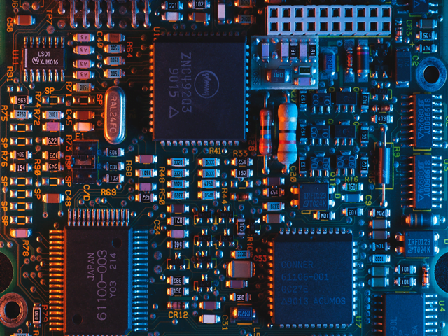
Electronic Circuit Board (PCB) Design & Production
Circuit Board Test Production Assembly Software PCB Design
Since 2020
Design Solutions
With more than 5 years of experience, we have designed more than 120 cards so far and have been in production processes. Hundreds of our cards work on different pitches 24/7.
So far, we have not encountered any problems with our cards due to design.
As Oxa Software Team, we are at your service for the circuit designs needed.
We meet your software and hardware needs with the most affordable prices on a project-based comprehensive.
You can contact us for a design or prototype.
Step by Step PCB Design
Your designs are realized step by step. Our services cover all electronic circuit design cards.
- Single-sided PCB
- Double-deck PCB
- Multi-layer PCB (up to 32 layers)
- Aluminum PCB
- Rigid-Flex (flexible) PCB
- Lead free PCB
- Through-hole coated PCB
- PCB with gold surface plating
- Stencil
- PCB string (PCBA) assembly
- PCB in military or medical standards
Step 1 - Simulation
Step 2 - Design
Step 3 - Production
Step 4 - Assembly
Step 5 - Test
Step 6 - Shipping
Simulation
A system computer conducts experiments to understand the behavior of the system or evaluate different strategies for the purpose of operating the system with this model after modeling in the environment, computer is a technique that evaluates through. Simulation, which has a very important place in the development and use of complex systems; is home to many areas such as analysis, testing, and evaluation. We offer unique solutions with our research and development studies in this regard.
PCB Design
The target product whose simulation is completed is taken to the design stage. Fabric production files required for production are produced. As the second stage, it is aimed to obtain the design to meet all the desired needs by considering all the details of the product in making the idea whose simulation is completed a reality.

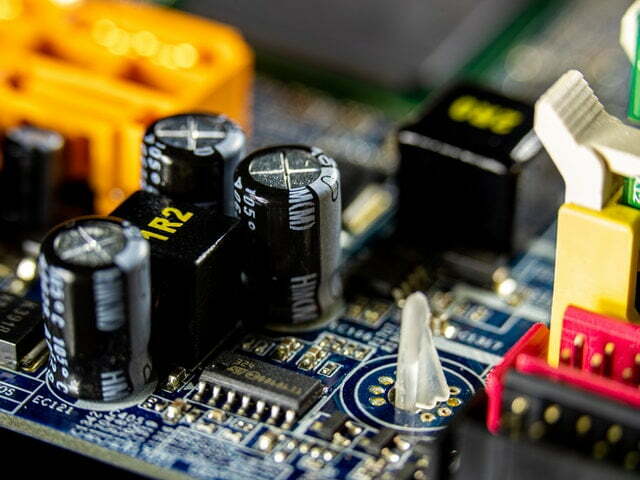
Production
After completing the design, the prototype working efficiency of the product and other criteria are tested. The circuit design, which successfully passed the tests and received approval, is taken to the mass production band. It is produced according to the number of units.
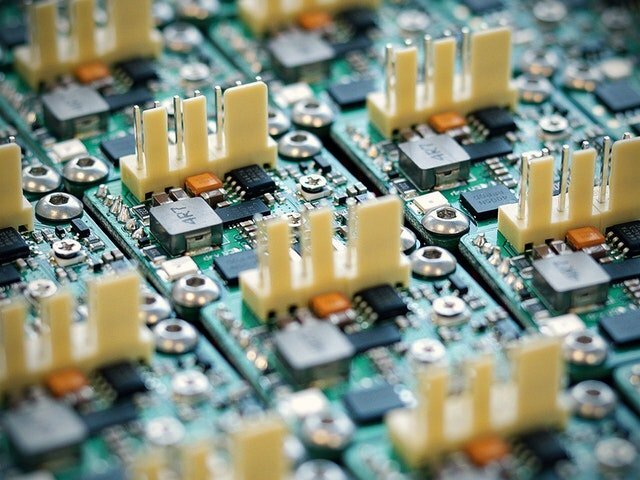
Assembly and Test
After production, other connections are completed and tested. The useful life of electronic devices is determined to be approximately 10 years in the industry. In this process, different tests are carried out in order to guarantee this period for machines or special uses. In order for the produced devices to be used for many years, durability tests against various industrial conditions are carried out in this process and are carried out in coordination with mass production.
Contact Form
What to Know in Electronic Circuit Board Design
What are the PCB design rules?
Designs are made within the framework of certain rules in order to brand and take a smooth place in the sector.
A professional circuit design should have as few errors as possible. Therefore, there are many rules in these designs. The most basic of these rules are; the diameter of the hole in the thickness of the paths, the distance between the holes, and the minimum distance between the roads.
In order to create a global and competitive product where production will be high, different standards must also be observed. We work in accordance with international standards to provide a better service and ensure quality.
What are international standards?
International standards are the rules specified in the designs for companies to comply with similar requirements. Standards are offered to the user for a material price. Price ranges ($70-$2000) vary according to the user’s preferred standards. Users can obtain standards as digital documents or in books. The information sold can be single-user or company-based.
You can reach hundreds of electronic standards used in many industrial devices today from this link.
What are the standards that contribute to us?
International standards are generally established through companies located in the United States and the UK, allowing products completed in many areas such as user safety, working conditions, design, and materials to pass tests on the product in order to enter international markets.
These rules all make the product durable and ensure that the product is best marketed in countries or associations such as CE and the Turkish Standards Institute Türk Standartları Enstitüsü (TSE). Otherwise, serious problems may be encountered by customs, sales, users, and marketing.
Hole diameter and path thickness
By what rules are hole diameters determined?
It is the minimum hole diameter of 0.3mm in one and two-layer circuits. 0.25mm hole diameter is preferred in circuits with four and above road layers. This rule is created entirely according to the capabilities of the manufacturer. We specify these rules to the design program, thereby minimizing our mistakes. Thanks to these rules, the time loss due to problems that may be encountered in production is prevented.
How are the road thicknesses determined?
Road thicknesses are selected taking into account current and voltage value. Of course, this information is not enough for road thickness. The road thickness is directly effective with the conducting material and conducting thickness of the electronic card whose production is decided. Copper is the preferred conducting material in electronic cards during the production phase. Materials may vary in materials where natural cooling is needed, such as lighting.
In designs, FR-4 material with a thickness of 1.6mm with 1oz (35um) copper conductor is generally preferred. The material may also vary according to the production request. For example, if you want to use FR-4 material is not suitable for PCB in antenna designs. At high frequencies, the loss is high and the desired data transmission distances cannot be achieved. Rogers-type material is used instead of FR-4. Increased losses due to increased frequency are minimized thanks to this material. A detailed difference between the two materials can be found here.
Electronic circuit board production
It is important to ensure that the materials produced are quality, the error rate is minimized and tested. Pcbway and Jlcpcb sites are preferred due to competitive prices. Pcbway Printing Circuit company, which is very successful in fast express card design in Turkey and provides fast service, can be preferred.
When can my completed electronic card be delivered?
Product delivery takes between 1 week and 1 month depending on the shipping process. In general, UPS cargo company is preferred for the designs to reach our company in the fastest way. If PCB production is in China, the average delivery time is 2 weeks.
Supply of electronic materials
It is important that original materials arrive during design. For this reason, companies such as Digikey, Mouser, and Farnell, which are widely used in material selection, are preferred. Özdisan Company, which stands out with its competitive prices, is preferred if productions are made completely domestically. The supply of materials depends entirely on the number of units of production and the target audience of the product that will be produced as a result of the design. Materials used in designs for difficult conditions are provided directly from distributors of manufacturers.
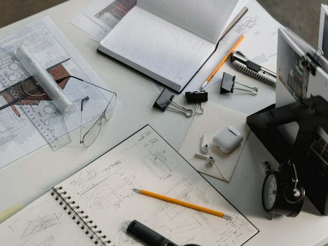
Design
There may be free software in electronic card design, as well as well-known software is preferred. The most widely used card design programs powered by user tools are Diptrace, Altium Designer, and Eagle. Altium Designer and Eagle are the leading companies in the industry. The Altium Designer program is mostly at the forefront of our designs. Different design programs can also be preferred if needed.
Why is documentation so important?
If the design planned to be prototyped is limited to one, there is no need to prepare documentation. If you have two or more designs and are designing dozens of cards in the future, it is worth preparing documentation. All circuit diagrams, descriptions, and rules are included in the document content. These rules are followed in the updates or different designs that are requested to be made later. Even if your customer and card design company change, if these rules are followed, you are bound by the rules, not the people.
For example, if you want to use you’ve made a quote from a company. After a while, the firm asked you for a different offer. Will the entire offer be changed or will the offer be forwarded by modifying a certain file? In such cases, the documents created during the design phase facilitate compatibility thanks to the rules they contain and it becomes simple to add and remove from the project. In this way, the yield increases. This shows us the importance of documentation.
It’s not a person-bound design, it’s a rules-based design. In your design work, the rules will help you avoid all subsequent problems. In this way, you will always be one step ahead of other companies.
Sincerely,
Oxa Hardware Team.