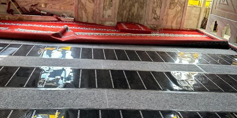
The most critical step for the long, safe life of a carbon film heater is cutting and connecting it correctly. A film cut in the wrong place will not work, and a poor connection leads to overheating, arcing and earth leakage. In this guide we explain step by step how to cut a carbon film heater and how to connect it.
Warning: Electrical connections must be made by a qualified electrician. This article is for information only.
Materials and Tools Required
- Carbon film and clamps (connection clips) of the right width
- Butyl or bitumen insulating tape (for film ends and connections)
- Supply cable of suitable cross-section
- Scissors or a utility knife, and crimping pliers
- Multimeter and insulation resistance tester (megger)
1. Cut the Film in the Right Place
Carbon film may only be cut along the marked cutting lines. These lines are in the transparent, carbon-free area between two carbon strips.
- Never cut through a carbon strip.
- Never cut the film lengthways (along the copper busbar); if the busbar is cut, the film will not work.
- The copper busbars at the cut end will be insulated later.

2. Fit the Clamps
- Position the clamp on the copper busbar with one leg between the film layers and the other outside the film.
- Make sure the clamp is in full contact with the copper busbar.
- Crimp it firmly with pliers; the clamp must not move.
- Each strip uses two clamps, one for each busbar.
3. Connect the Cable
Strip the end of the supply cable and crimp it into the clamp. The cable cross-section must be chosen according to the circuit’s total current. Each strip can be fed by its own cable, or strips can be connected to a common parallel feeder.
Important: Film strips are always connected in parallel. Never connect them in series.
4. Insulate Connections and Ends
- Apply a piece of insulating tape above and below each clamp connection so it is completely sealed.
- Also seal the copper busbars at the unconnected opposite end of the film with insulating tape.
- Press the tape down firmly so it does not create bumps.

5. Thermostat and Protection
The circuit must be supplied through a suitable circuit breaker, a 30 mA RCD and a thermostat with sufficient current capacity. The floor sensor is placed between two strips. Details: thermostat selection and floor sensor.
6. Testing and Commissioning
- Resistance measurement: Measure the resistance of each strip with a multimeter. The expected value can be estimated as 230² ÷ strip power; values that differ greatly indicate a faulty connection.
- Insulation test: Measure the insulation resistance between the film circuit and earth.
- Heat check: Run the system briefly and check that every strip heats evenly.
- Lay the floor covering only after testing is complete.
Common Mistakes
- Cutting through a carbon strip
- Fitting the clamp to the top layer of the film only
- Failing to insulate connections and cut ends
- Connecting strips in series
- Laying the floor covering without testing
These mistakes lead to tripped breakers and heating failures. See our articles on tripping breakers and a heater that won’t heat.
Conclusion
Carbon film must only be cut along the cutting lines, clamps must be fitted firmly, every connection insulated and strips connected in parallel. See our installation guide for the full process, or contact us for materials and installation support.